ESP ZeroCode AI · Community
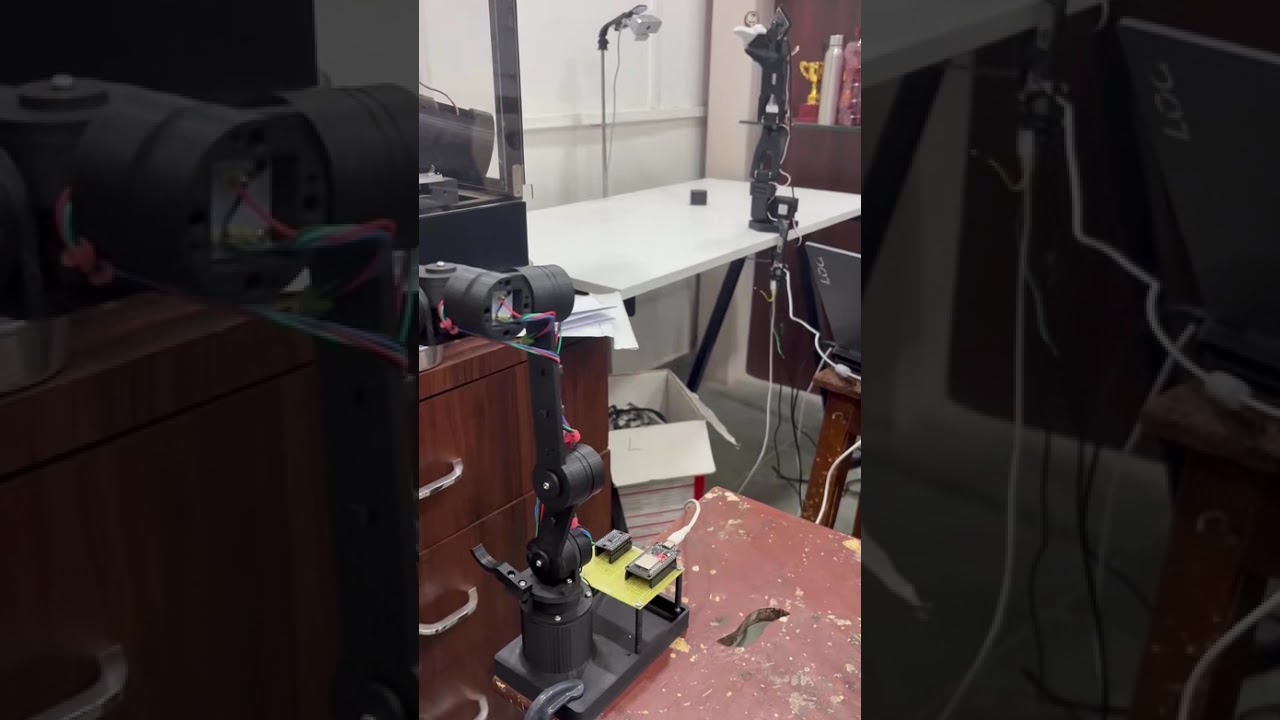
Hacky-Leader
Build a reliable real-time teleoperation system connecting an ESP32-based, encoder-driven Hacky Leader Arm to a physical SO101 follower using LeRobot. Integrate encoder firmware, serial communication, joint mapping, calibration, and safe motion control to enable accurate leader-to-follower movement.
What it does
- Six-joint sensing — six AS5600 magnetic angle sensors read over one I2C bus through a TCA9548A multiplexer (mux 0x70, sensors 0x36), one channel per joint
- I2C wiring — SDA GPIO18, SCL GPIO19, 3.3 V supply for the mux and the encoder boards (non-standard pins, set explicitly in firmware)
- Encoder stream — samples all six channels at 100 Hz and prints one ASCII line per sample: six comma-separated 12-bit angles (0–4095), -1 for a channel that failed to read
- Serial link — USB serial at 115200 baud, line-oriented, no command/response handshake; the host just opens the port and reads
- Startup diagnostic — on boot, scans all six mux channels, verifies an AS5600 answers and reports magnet-detected status per joint, and reports the result on the serial line before streaming starts
- Status feedback — this board has no on-board user LED, so controller state (booting / diagnostic failed / streaming) is reported on the serial line; an external status LED is optional
- Bad-channel handling — a failing channel never stops the stream: it keeps sending -1 in its position, and a one-line warning naming the bad channel is inserted into the stream once per second until it recovers
Manual
Device Type
Encoder leader-arm controller — the sensing half of a leader/follower teleoperation pair. Six joints of a hand-built leader arm are measured by absolute magnetic encoders and published as a line-oriented ASCII stream over USB, so a host running LeRobot can drive a physical SO101 follower arm to mirror the operator's motion in real time. It is a bench instrument, not a smart-home device: no Wi-Fi, no cloud, no framework integration. The ESP32 deliberately does no robot control itself — the host owns joint mapping, direction signs, offsets and follower calibration.
Hardware
chip: esp32 — board: ESP32-DevKitC (generic 30-pin ESP32 dev board, USB serial on the dev board's own UART) — gpios: gpio: GPIO18 — role: I2C SDA to the TCA9548A multiplexer — note: non-standard I2C pin — must be set explicitly in firmware, not the default 21 · gpio: GPIO19 — role: I2C SCL to the TCA9548A multiplexer — note: non-standard I2C pin — must be set explicitly in firmware, not the default 22 · gpio: GPIO1 / GPIO3 — role: console UART0 — reserved, nothing wired · gpio: GPIO6–GPIO11 — role: internal SPI flash — not available on the header · gpio: GPIO0 — role: on-board BOOT button — left unused (no input behaviour required) — peripherals: part: TCA9548A — role: 8-channel I2C multiplexer at address 0x70; channels 0–5 each carry one AS5600 — notes: All six sensors share address 0x36, which is why the mux exists. Channels 6 and 7 are unused. RESET and the A0–A2 address straps are left at their board defaults. · part: 6x AS5600 — role: magnetic absolute angle sensors at 0x36, one per joint (six joints total) — notes: 12-bit single-turn absolute output, 0–4095 counts per revolution (≈0.088° per count). Each sensor is read from the raw-angle register; no filtering/IIR is enabled in the sensor, because smoothing belongs on the host where the control loop can see the trade-off. Output pin (analog/PWM) is not used — everything goes over I2C. · part: Power — role: 3.3 V and GND for the mux and all six encoder boards, taken from the dev board's 3V3 pin — notes: AS5600 and TCA9548A are both 3.3 V parts; do not power the encoder boards from 5 V. Whole assembly is USB bus powered.
Inputs
kind: sensor — label: Six arm joints — hardware: AS5600 magnetic angle sensors behind the TCA9548A, addressed one channel at a time — behavior: Each joint is sampled once per stream line. The value is the sensor's absolute 12-bit angle (0–4095) at the time of the read, so joint position is known immediately after power-up with no homing motion. Readings are reported in channel order 0–5, which the host maps to joint names. There is no physical input on the device itself — no button, no touch, no calibration switch.
Outputs
kind: serial — label: Joint-angle stream — hardware: USB serial (UART0 via the dev board's USB-serial bridge), 115200 baud, 8N1 — behavior: One sample line per 10 ms tick (100 Hz nominal): six comma-separated integers, channel order 0–5, each 0–4095, or -1 if that channel could not be read this tick. Lines are LF-terminated ASCII. A line that fails validation on the sensor side still emits with -1 in the affected slot, so the field count is always six and the host can parse positionally. · kind: serial — label: Diagnostic / warning lines — hardware: same USB serial stream — behavior: Every non-data line starts with '#' so the host can drop it with one prefix test. Used for the boot report, for the once-per-second bad-channel warning, and for any recoverable bus trouble. Examples: '# boot: mux ok, 6/6 sensors, magnets ok', '# warn: channel 2 no response (3 ticks)'. Nothing is ever printed inside a data line. · kind: indicator — label: Board LED — hardware: none fitted — this dev kit variant has no user LED — behavior: Controller state is therefore observable only on the serial line. An external LED on a spare pad is optional and not part of the base build; if one is added later, booting = slow blink, diagnostic failure = fast blink, streaming = solid.
Connectivity
stack: bare USB serial (no framework, no Wi-Fi, no network) — transport: USB CDC/UART bridge on the dev board, appears as /dev/ttyUSB0 on the host — purpose: the only channel in or out — carries the joint-angle stream and the diagnostic lines; the device also flashes over the same port
Business Logic
powerOnBehavior: On power-up or reset: I2C bus and mux are brought up, then all six channels are probed once — mux reachable, an AS5600 ACKs on each of channels 0–5, and each sensor reports a magnet detected and its AGC/status sane. The result is printed as a single '#' report line (how many of six sensors answered, which channels are bad, which joints have no magnet). Streaming begins immediately after the report regardless of the outcome — a failed channel simply starts emitting -1. There is no waiting state and no button to press. — automationRules: Sample all six channels once per 10 ms and emit one line — the loop is time-driven, not event-driven; a slow or absent sensor does not stretch the period beyond the read timeout. · While any channel stays unreadable or magnet-less, insert exactly one '#' warning line per second naming the affected channel(s), interleaved between data lines. Stop warning as soon as the channel reads healthy again — recovery is automatic and silent. · Never emit a partial or short data line: if a read fails, that slot is -1 and the other five still go out. — dayToDayOperation: Power the arm from USB, open /dev/ttyUSB0 at 115200 on the host, and read lines. The operator physically moves the leader arm; the angles change on the next sample within 10 ms and the host mirrors them onto the SO101 follower. A joint that suddenly sticks at -1 means that encoder's magnet or wiring moved — the '#' warning names which channel, and the arm keeps streaming meanwhile. No interaction with the device is ever required during a session; nothing needs to be re-plugged to clear a transient sensor fault.
Factory Reset
trigger: there is no user-facing reset gesture — the device holds no persistent state (no Wi-Fi credentials, no stored calibration, no settings) — effect: a power cycle or an EN-press fully resets it; the host re-opens the port and the stream resumes. Joint offsets and direction signs live in the host's LeRobot configuration, so a re-flash or board swap does not lose calibration.
Failure Modes
scenario: ESP32 not plugged in / USB cable is charge-only — behavior: no port appears on the host; on the device side nothing to report — this is the first thing to check when /dev/ttyUSB0 is missing · scenario: USB unplugged or host closes the port mid-session — behavior: firmware keeps sampling and writing; writes fail harmlessly and the stream simply resumes when the port is opened again, with no reset needed · scenario: TCA9548A not answering at 0x70 — behavior: boot report says the mux failed; every sample line is '-1,-1,-1,-1,-1,-1' and the once-per-second warning identifies it as a bus-level fault rather than one joint — this points at SDA/SCL wiring or 3V3 · scenario: one AS5600 dead, unplugged, or on a bad channel — behavior: that joint reads -1 every tick; the other five keep streaming correctly; a '#' warning names the channel once per second · scenario: magnet missing, weak, or too far from the sensor — behavior: the boot report flags it as a magnet problem rather than a bus problem; while it persists that channel emits -1 and is named in the warnings · scenario: bus glitch / a channel locks the bus — behavior: the read is given up after a short timeout instead of blocking the loop, the affected slot emits -1, and the bus is recovered on the next tick — the 100 Hz cadence is preserved on a best-effort basis · scenario: host-side mismatch (port is the follower instead of the leader, or baud rate wrong) — behavior: device side is unchanged and still streaming; the fix is on the host, which is why the boot report and the -1 pattern exist to make the two cases distinguishable
Power Management
batteryPowered: false — note: USB bus powered from the host; no battery, no deep sleep, no wake sources. The device is intended to be powered whenever the host is doing teleoperation.
Custom Behavior
serialProtocol: Line-oriented ASCII, one line per 10 ms. DATA line: exactly six comma-separated integers, channel order 0–5, each 0–4095 or -1, LF-terminated. META line: begins with '#', human-readable text, may appear anywhere between data lines. The protocol is one-way (device → host) apart from the flashing port itself — the firmware never parses input, so the host cannot command the device. Booting the device does not require the host to send anything. — samplingBudget: Six sensors through one mux is the reason for the 400 kHz fast-mode bus: a full sweep of six single-register reads has to fit inside the 10 ms tick with room to spare, so the firmware must run the bus in fast mode and set a short per-read timeout.
Published 23 Oct 2026 · version 2
Firmware and source licensed Apache-2.0; photos and text CC-BY-4.0.
The firmware includes open-source software — open-source licences and notices; some components may be used only with Espressif chips.
Built with ESP ZeroCode AI — describe a device, get production firmware.
Terms of Service · Privacy Policy