ESP ZeroCode AI · Community
button indicator
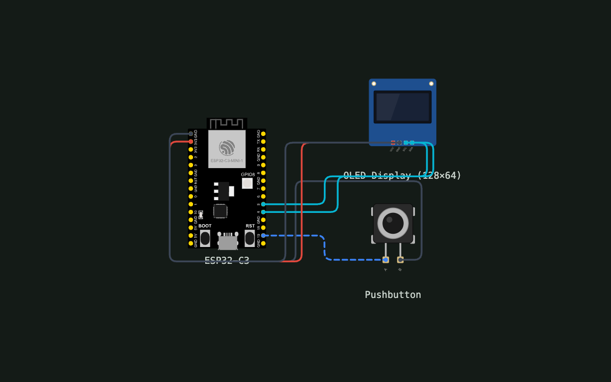
I want a basic firmware which displays over the OLED whether the button is pressed or released. Button should get triggered on GPIO interrupts
What it does
- Button Input — GPIO 19 Interrupt
- OLED Display — SSD1306 I2C
- Real-time State Display
- Logging — Button Press Events
- Logging — Display Update Status
Manual
Device Type
Standalone button-state indicator — displays whether a physical pushbutton is pressed or released on a small OLED screen in real time.
Hardware
chip: ESP32-C3 — board: ESP32-C3-DevKitM-1 — gpios: pin: GPIO19 — function: Button input (active-LOW) — mode: Input with internal pull-up, triggers GPIO interrupt on falling edge · pin: GPIO4 — function: I2C SDA — mode: I2C bus (with pull-up, 100 kHz standard mode) · pin: GPIO5 — function: I2C SCL — mode: I2C bus (with pull-up, 100 kHz standard mode) — peripherals: name: Pushbutton (tactile switch) — interface: GPIO19 + GND — behavior: Momentary switch; pressing connects GPIO19 to GND (active-LOW logic). State changes logged with timestamp. · name: OLED Display (SSD1306, 128×64) — interface: I2C (GPIO4 SDA, GPIO5 SCL) — behavior: Monochrome display; shows button state as text ('PRESSED' or 'RELEASED'). Each write attempt is logged (success/failure). · name: Serial UART (USB) — interface: Built-in UART0 (115200 baud, 8N1) — behavior: Console output for debugging logs. Shows button events, display updates, and any errors.
Inputs
kind: Button (GPIO interrupt) — label: Pushbutton on GPIO19 — hardware: Tactile momentary switch, active-LOW (GND when pressed) — behavior: Firmware detects falling edge (button pressed) and rising edge (button released) via GPIO ISR. Debounced over ~20ms in software to eliminate contact bounce.
Outputs
kind: OLED text display — label: Status text on 128×64 monochrome OLED — hardware: SSD1306 OLED module on I2C bus — behavior: Displays 'PRESSED' when button is held, 'RELEASED' when button is released. Text updates immediately after each debounced GPIO edge. · kind: Serial console logs — label: UART debug output — hardware: Built-in USB serial (default UART0 at 115200 baud) — behavior: Logs button state changes (PRESSED/RELEASED with timestamp) and OLED update success/failure. Viewable via serial monitor.
Business Logic
powerOnBehavior: On reset, firmware initializes I2C bus, GPIO19 interrupt handler, and serial logging. Logs 'System initialized' message. OLED displays initial button state (PRESSED or RELEASED based on GPIO19 level at startup). Ready for input immediately. — dayToDayOperation: User presses and releases button repeatedly. Each button state change (detected via GPIO interrupt after debounce) triggers: (1) a log message with button state and timestamp, (2) an OLED update attempt, (3) a log of the update result (success or I2C error). Developer watches serial console to monitor behavior and diagnose issues.
Failure Modes
scenario: Power loss — behavior: Device resets; on reboot, firmware logs 'System initialized' and displays current button state. Resumes monitoring interrupts. · scenario: OLED display fails or disconnected — behavior: GPIO interrupt handler still fires and firmware logs button state changes. I2C write fails; firmware logs 'OLED update failed: I2C error' or similar. Developer can diagnose via serial logs. · scenario: GPIO19 pin shorted to 3V3 or left floating — behavior: Internal pull-up holds the line HIGH (RELEASED state) if floating; if shorted to 3V3, GPIO reads HIGH (RELEASED). Interrupt triggers on changes only. Logs reflect the observed state transitions (or lack thereof).
Published 5 Oct 2026
Built with ESP ZeroCode AI — describe a device, get production firmware.
Terms of Service · Privacy Policy