ESP ZeroCode AI · Community
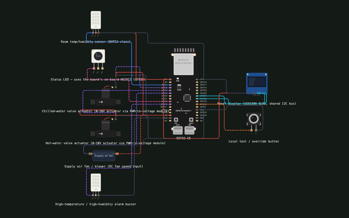
Air Conditioning System@Pharma
Air conditioning system should adjust room temperature and humidity based on the no.of occupancy level in the room so as to optimize the energy spent on air conditioning.
What it does
- Room temperature & humidity sensing (DHT22-class sensor, GPIO4); default control spec 22 ± 2 °C and 50 ± 10 %RH
- Occupancy = biometric counting at the room entry: each authorised person's biometric check increments the in-room count (room holds up to ~15 people)
- Occupancy count obtained over Wi-Fi from the door biometric system with no occupancy hardware on our board — supports BOTH polling its count endpoint and accepting a pushed count (OEM interface not yet fixed)
- BMS reporting: controller runs a small local HTTP server on Wi-Fi/LAN that the site BMS polls (via its BACnet/OPC gateway) for temperature, humidity, occupancy, valve/fan positions and alarm state
- Setpoints (temperature, humidity, occupied/unoccupied setback) are remote-configurable over the network, with the factory defaults as fallback
- Commissioning over USB serial terminal (115200 baud): fitter enters Wi-Fi credentials, the biometric system's address and network settings; kept in flash
- Hold the local button for 5 s to wipe credentials/settings and return the device to setup
- Occupancy tiers drive the temperature/humidity setpoints (empty room = setback, busy room = tighter setpoint)
- Modulates chilled-water flow (cooling coil) via a 0-10V proportional valve actuator on GPIO5
- Modulates hot-water flow (reheat / heating coil) via a 0-10V proportional valve actuator on GPIO6
- Modulates supply air flow (EC fan speed input, PWM on GPIO7)
- Panel installation: screw-terminal breakout board for the IO, powered from the existing 24 V control supply via a DC-DC converter to 5 V
- Small OLED display in the room panel showing live temperature, humidity and current occupancy count (I2C on GPIO20/21)
- Alarms when temperature leaves 20-24 °C or humidity leaves 40-60 %RH — audible buzzer on GPIO10, LED flashes red
- Optimizes energy spent on air conditioning (setpoint setback + reduced airflow when the room empties)
- Failsafe: valves close and fan drops to minimum if the network feed or the controller is lost, so a fault can never over-cool/over-heat the room
- Status LED (board WS2812, GPIO8) reports state; local button (GPIO18) triggers a test cycle
Manual
Device Type
A room-level HVAC controller for a pharmaceutical facility. It sits in the plant panel of a small AHU/FCU serving one occupied room (capacity ~15 people, biometric access control) and trims the room's air conditioning to the number of people actually inside, so cooling, reheating and air movement only happen at the level the room needs. It is a standalone ESP-IDF device — no smart-home stack; it talks to the site's door biometric system for occupancy and to the site BMS for reporting.
Hardware
chip: ESP32-C6 (ESP32-C6-DevKitC-1 board: Wi-Fi 6, on-board WS2812 RGB LED on GPIO8, BOOT button on GPIO9) — gpios: pin: GPIO4 — use: Temperature/humidity sensor data (DHT22-class, 1-wire timing) · pin: GPIO5 — use: Chilled-water valve actuator command (PWM into a PWM-to-0-10V module) · pin: GPIO6 — use: Hot-water / reheat valve actuator command (PWM into a PWM-to-0-10V module) · pin: GPIO7 — use: Supply air fan speed command (PWM into the EC fan's 0-10V/PWM speed input) · pin: GPIO8 — use: On-board WS2812 status LED (board-owned, not wired externally) · pin: GPIO9 — use: On-board BOOT button (board-owned; not used as the user control) · pin: GPIO10 — use: Alarm buzzer (active buzzer + transistor, or piezo on LEDC) · pin: GPIO18 — use: Local test / override button, other side to GND, internal pull-up · pin: GPIO20 — use: I2C SDA to the panel OLED · pin: GPIO21 — use: I2C SCL to the panel OLED — peripherals: part: DHT22-class temperature/humidity sensor — role: room temperature and relative humidity measurement — wiring: DATA → GPIO4, VCC → 3V3, GND → GND; 10 kΩ pull-up on DATA · part: 2 × 0-10V proportional valve actuator (cooling coil, heating coil) — role: modulating chilled-water and hot-water flow — wiring: each actuator driven from a PWM-to-0-10V module: PWM from GPIO5 / GPIO6; actuator supply from the panel's 24 V, powered separately from the ESP32 · part: EC supply-air fan — role: modulating supply air flow — wiring: speed input from GPIO7 through the same PWM-to-0-10V module; 10 V reference from the fan's own supply · part: SSD1306 OLED 128x64 (I2C) — role: local panel readout — wiring: SDA → GPIO20, SCL → GPIO21, VCC → 3V3, GND → GND; address 0x3C · part: Active buzzer — role: audible alarm — wiring: IN → GPIO10 (plus NPN transistor if the buzzer draws more than ~12 mA), GND → GND · part: Momentary button — role: local test / override / factory reset — wiring: IN → GPIO18, other side → GND, internal pull-up · part: Screw-terminal breakout board + 24 V→5 V DC-DC converter — role: field wiring and power — wiring: panel 24 V control supply → DC-DC → 5 V to the devkit's 5V pin; all IO presented on screw terminals
Inputs
kind: sensor — label: Room temperature & humidity — hardware: DHT22-class sensor on GPIO4 — behavior: read every 5 s (two consecutive successful reads required); a bad read is discarded and flagged if it persists for 60 s · kind: network — label: Occupancy count — hardware: door biometric system over Wi-Fi — behavior: the controller polls the configured biometric URL every 5 s for a JSON person count; on an empty room the count settles to 0. If the biometric system instead pushes counts, the controller accepts an inbound count update on the same link. Counts are clamped to 0-15 and only updated while the biometric system is reachable; a stale feed (no update for 10 min) is treated as unknown occupancy · kind: button — label: Local test / override button — hardware: push button on GPIO18 — behavior: short press = run a self test (drive both valves 0→100→0 % and the fan 0→100→0 % over ~10 s while showing progress on the OLED, so a fitter can confirm the actuators move); hold 5 s = wipe Wi-Fi/biometric settings and reboot into the serial setup prompt
Outputs
kind: actuator — label: Chilled-water valve — hardware: 0-10V proportional actuator, PWM on GPIO5 — behavior: 0-100 % opening from the cooling PID demand; 0 % when the room is at/below the active cooling setpoint, when the reheat demand is active, or in failsafe · kind: actuator — label: Hot-water (reheat) valve — hardware: 0-10V proportional actuator, PWM on GPIO6 — behavior: 0-100 % opening from the heating/reheat demand only; held at 0 % whenever the cooling coil is open, with a dead-band so the two valves never fight (cooling is stepped to 0 % first, then reheat is allowed) · kind: actuator — label: Supply air fan — hardware: EC fan speed input, PWM on GPIO7 — behavior: minimum speed when the room is unoccupied or conditions are in band; scaled up with occupancy tier and with the size of the active demand; full speed for 60 s on alarm; minimum speed in failsafe · kind: display — label: Panel OLED — hardware: SSD1306 128x64 over I2C — behavior: line 1: room temperature and humidity; line 2: occupancy count and tier; line 3: control state (Cooling / Heating / Idle / Alarm / Failsafe / No feed) and the two valve/fan percentages; backlight-free, refreshed once a second · kind: indicator — label: Status LED (on-board WS2812) — hardware: GPIO8 — behavior: blue breathing = normal control; green = room empty / setback active; yellow = no Wi-Fi or no occupancy feed (running on last known count); red flashing = temperature or humidity alarm; purple = setup mode awaiting serial configuration · kind: audible — label: Alarm buzzer — hardware: buzzer on GPIO10 — behavior: sounds an intermittent beep while temperature is outside 20-24 °C or humidity outside 40-60 %RH; silent in normal operation; can be silenced for 10 minutes by a short button press without cancelling the alarm state
Connectivity
stack: ESP-IDF Wi-Fi STA — transport: 2.4 GHz Wi-Fi — purpose: reach the door biometric system for the occupancy count, and serve the BMS read endpoint · stack: HTTP client — transport: TCP/HTTP over Wi-Fi — purpose: poll the biometric occupancy endpoint every 5 s (and accept a pushed count if the biometric system pushes) · stack: HTTP server — transport: TCP/HTTP over Wi-Fi, default port 8080 — purpose: read-only endpoint the site BMS (through its BACnet/IP or OPC gateway) polls for temperature, humidity, occupancy, valve and fan positions, active setpoints and alarm/failsafe state; also accepts setpoint writes from the BMS
Commissioning
method: USB serial terminal (115200 8N1) with NVS-persisted settings — payload: Wi-Fi SSID, Wi-Fi password, biometric occupancy feed URL, optional BMS read port (default 8080) — instructions: In the plant room, plug a laptop into the board's USB port and open a serial terminal at 115200 baud. On first boot (or after a 5 s button hold) the firmware prints a short setup prompt and asks for: the plant Wi-Fi network name and password, the address of the biometric occupancy feed (e.g. http://10.0.0.45/api/occupancy), and optionally the port the BMS should poll. Values are written to NVS and the device reboots; the status LED shows purple while waiting and turns blue when it joins the network and receives its first valid occupancy count. The same prompt can be re-entered later to change settings without erasing them (type 'setup').
Business Logic
powerOnBehavior: On power-up the controller holds both valves at 0 % (fail-closed) and the fan at minimum, runs a 5 s sensor/OLED self-check (a red LED flash indicates a failed sensor), then joins Wi-Fi. Until it has both a valid temperature reading and a valid occupancy count it stays in a safe idle state — valves closed, fan at minimum airflow, LED yellow, OLED showing 'starting/no feed'. Once both feeds are good it enters normal control. — automationRules: Occupancy tiers: 0 people → setback (unoccupied) setpoints (28 °C / 60 %RH max, fan minimum); 1-5 → stage 1 setpoints; 6-10 → stage 2; 11-15 → full-occupancy setpoints (22 °C / 50 %RH). Tier changes follow the count immediately, but with a 3-minute up-transition / 10-minute down-transition delay so a person briefly stepping out does not shed the conditioning. · Free cooling / dead-band control: the cooling PID acts whenever temperature is above the active cooling setpoint + 1 °C, the reheat PID whenever it is below the active setpoint − 1 °C, and the fan follows the larger of the two demands; inside the dead-band both valves sit at 0 % and the fan runs at minimum — this is where the energy saving is realised. · Humidity priority: if relative humidity rises above the active RH limit (e.g. 50 % + 5 % for high occupancy) while the room is already cool, the cooling valve is opened further (and the fan raised) to wring out moisture rather than relying on reheat. · Anti-short-cycle: a valve that has reached a new opening is held for at least 60 s before the controller may reverse the demand, protecting the actuators. · Alarm logic: temperature outside 20-24 °C or humidity outside 40-60 %RH, sustained for 5 minutes, latches an alarm — red LED flash + buzzer; the condition also appears in the BMS read data. A short button press silences the buzzer for 10 minutes; the alarm clears by itself once the room is back in band. · Remote setpoints: the BMS may write the occupied/unoccupied temperature and humidity setpoints (and the tiers' targets) through the read endpoint; writes are range-checked (18-30 °C, 30-70 %RH) and stored in NVS so they survive a power cut. With no BMS write, factory defaults apply. · Stale-feed handling: if the occupancy count stops updating for 10 minutes the controller keeps the last known tier only for a further 10 minutes, then assumes the unoccupied setback (fail to the cheapest safe state) and flags 'no feed' on the OLED and in the BMS data. · Test mode: the button-driven test forces the actuators through their range without changing the setpoints; control resumes automatically when the test ends. — dayToDayOperation: Nobody operates the controller day to day. It sits in the panel, reads the biometric count of the room 12 times a minute, and quietly moves the chilled-water and hot-water valves and the supply fan to hold the pharma-comfort target for the number of people inside. A pane of glass in the panel door shows the OLED with live temperature, humidity, headcount and what the valves are doing. When a room is empty the setpoint goes slack and airflow drops, which is where the electricity and chilled-water savings come from; when a group arrives the controller tightens the setpoint over the next few minutes. The BMS sees the same numbers on its own trend screens.
Factory Reset
trigger: Hold the local button for 5 seconds (or type 'reset' at the serial prompt) — effect: Wi-Fi credentials, the biometric feed address and any BMS-supplied setpoints are erased from NVS; the device reboots into setup mode (purple LED) and waits for the serial prompt. Actuators go to their fail-safe positions during the reset, so the room is never left with a valve stuck open.
Failure Modes
scenario: Wi-Fi / network down — behavior: the controller keeps the last known occupancy tier for 10 minutes, then falls back to the unoccupied setback (valves closed, fan minimum), LED yellow, 'no feed' shown on the OLED; the BMS read endpoint is unreachable, so the BMS will see the device drop out · scenario: Biometric system reachable but returning no/garbage data — behavior: invalid payloads are ignored; the last valid count ages out after 10 minutes of silence and the device moves to the unoccupied setback, flagging 'no feed' · scenario: Temperature/humidity sensor fails or is unplugged — behavior: the controller cannot safely control, so it closes both valves and drops the fan to minimum, flashes the LED red and shows 'sensor fault'; the alarm is also exposed in the BMS read data. It recovers automatically when the sensor returns · scenario: BMS stops polling us — behavior: no effect on control — the read endpoint is passive; the controller continues to run and logs nothing. Only the internal OLED and LED indicate state · scenario: Mains/power blip (24 V control supply) — behavior: on power return the device boots to the fail-safe state (valves closed, fan minimum) and re-establishes Wi-Fi and the occupancy feed before resuming control; setpoints are preserved in NVS · scenario: Actuator unplugged or wired wrong (no feedback expected) — behavior: the controller still drives its output; the fitter notices in the self test that the valve/fan does not move and the OLED's reported demand does not match the physical response · scenario: Firmware crash / watchdog — behavior: the watchdog resets the device; the PWM outputs are driven to 0 % during boot, so an unmanaged reset cannot leave a valve held open
Power Management
batteryPowered: false — note: Mains-powered from the panel's 24 V control supply through a DC-DC converter to 5 V. Wi-Fi stays connected permanently (the occupancy feed is polled every few seconds, so no light sleep); the OLED refreshes once a second and dims nothing. Typical draw ~100-150 mA at 5 V.
Custom Behavior
The product's own logic is the occupancy-driven setpoint/fan strategy: the biometric headcount at the door is the primary control input, translated into tiers that slacken or tighten the comfort target and the airflow, with anti-short-cycle protection on the valves and a fail-to-cheapest-safe-state rule whenever the occupancy feed, the sensor or the network is lost. The controller is read-and-write accessible from the site BMS over a simple HTTP endpoint (the OEM BACnet/IP or OPC gateway on site does the protocol translation), which is how the facility team trends the room and adjusts setpoints without touching the panel.
Published 16 Oct 2026
Firmware and source licensed Apache-2.0; photos and text CC-BY-4.0.
The firmware includes open-source software — open-source licences and notices; some components may be used only with Espressif chips.
Built with ESP ZeroCode AI — describe a device, get production firmware.
Terms of Service · Privacy Policy